The Ultimate Metric of Crystal Perfection
When evaluating sapphire substrates for advanced semiconductor or high-power optical applications, macroscopic inspections (like checking for cracks or bubbles) are simply not enough. To truly understand the structural integrity of the crystal lattice, material scientists turn to the ultimate metric: Etch Pit Density (EPD).
A sapphire EPD test reveals the microscopic “DNA” of the crystal. By subjecting the wafer to aggressive sapphire chemical etching, engineers can force hidden lattice imperfections to reveal themselves on the surface. For top-tier R&D scientists and QC professionals, decoding these etch pits is the key to pushing the boundaries of epitaxial yield and optical performance.
1. What is a Dislocation? The Genesis of Lattice Imperfection
At the atomic level, a perfect sapphire crystal is a continuous, unbroken three-dimensional grid of Aluminum and Oxygen atoms. A dislocation is a one-dimensional line defect where this perfect atomic grid is interrupted or misaligned.
But how do these dislocations form in an environment as controlled as a high-temperature growth furnace?
Seed Inheritance: The crystal growth process begins with a small “seed” crystal. If this seed already contains dislocations, those defects will propagate and multiply into the new boule as it grows.
Solid Particle Contamination: During the melt phase, if an insoluble solid particle (like a speck of stray tungsten or molybdenum from the hot zone) falls near the solid-liquid interface, the sapphire lattice must grow around it, causing massive local atomic distortion.
Thermal Stress and Lattice Slip: Sapphire crystallization involves extreme temperature gradients. As the boule cools, differential thermal contraction generates massive internal stress. To relieve this stress, entire planes of atoms may slide past one another. This “lattice slip” creates dense networks of dislocations.
When these dislocations terminate at the polished surface of a wafer, they become the “outcrops” that we analyze during EPD testing.
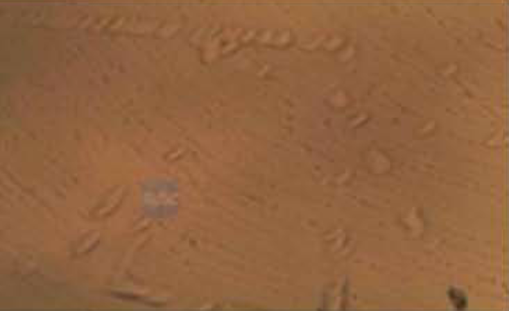
2. The Escalation: Formation of Sapphire Grain Boundaries
If a dislocation is a 1D defect, a grain boundary is a 2D catastrophe.
When sapphire dislocation density becomes too high, the individual dislocations begin to interact and group together to lower the crystal’s overall strain energy. If the crystallization rate is pushed too fast, or if impurities continuously aggregate at the growth interface, the atomic arrangement simply cannot maintain a single, unified orientation.
The result is a grain boundary sapphire structure. The crystal essentially fractures into sub-grains—distinct microscopic domains that are slightly tilted or misoriented relative to one another.
The Technical Consequence: In optical applications, a grain boundary acts as a severe refractive interface, causing massive polycrystalline dispersion and beam splitting. In semiconductor applications, growing GaN across a sapphire grain boundary guarantees a lethal fault line in your epitaxial layer.
3. Expert Q&A: Decoding the EPD Micrograph
The following insights are drawn directly from our engineering team’s recent technical review sessions, addressing the most complex questions regarding EPD visual analysis.
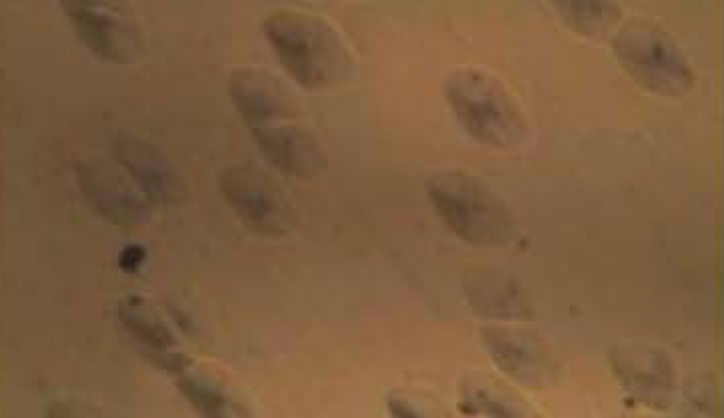
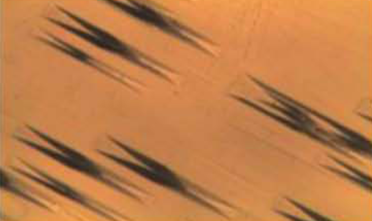
Q1: Why are C-plane (0001) etch pits triangular?
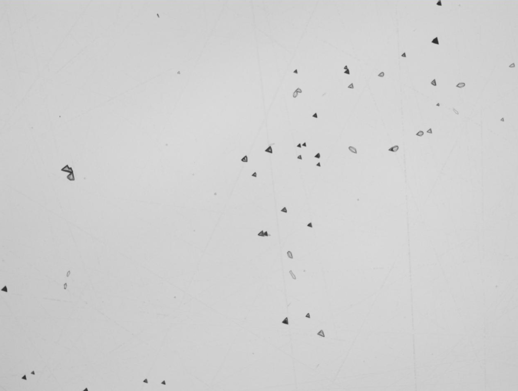
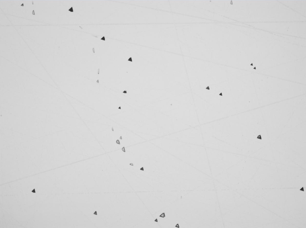
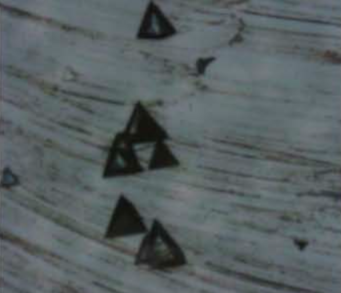
The Science: When you look at an EPD micrograph of a C-plane sapphire wafer, the etch pits are perfectly geometric triangles. This is not a random occurrence; it is a direct manifestation of the crystal’s mathematical symmetry.
Sapphire belongs to the trigonal crystal system. The C-axis has a three-fold rotational symmetry. When the wafer undergoes sapphire chemical etching (typically using a molten KOH/NaOH mixture or hot phosphoric/sulfuric acid), the etchant does not dissolve the crystal equally in all directions. Instead, it aggressively attacks the high-energy dislocation sites, dissolving the material along the specific crystallographic planes that offer the least resistance. Because of the three-fold symmetry of the basal plane, this anisotropic etching naturally carves out an inverted three-sided pyramid—making C-plane etch pits triangular.
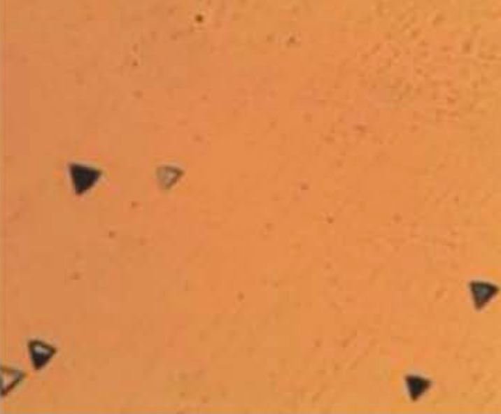
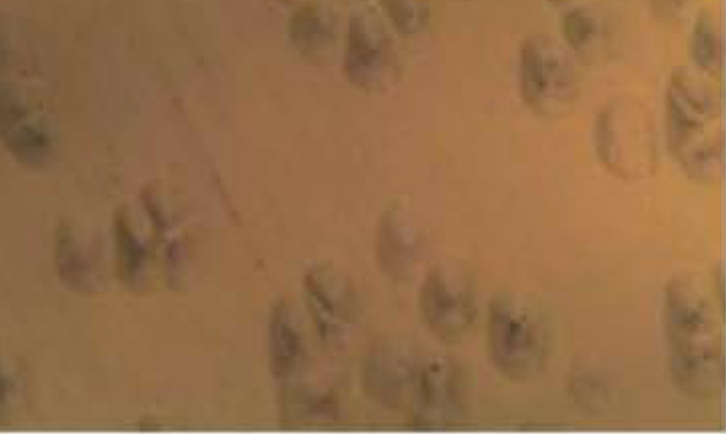
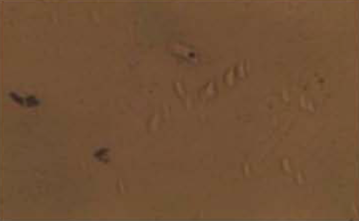
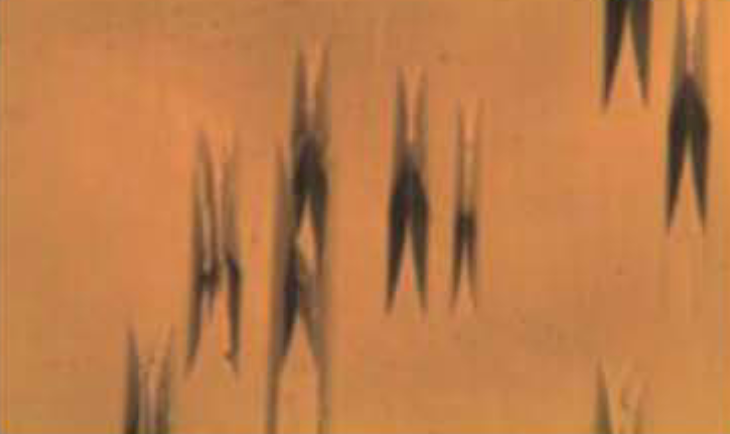
Q2: Why do the pits appear as varying shades of black and white under the microscope?
The Science: A common misconception is that the black and white spots represent different types of defects (e.g., edge vs. screw dislocations). In reality, the contrast is primarily a topographical and chemical development effect.
Not all dislocations hold the same amount of strain energy. A severe dislocation will etch much faster and deeper than a minor one. Because the pits vary in depth and volume, they retain different amounts of the chemical etchant/developer. When viewed under an optical microscope (often utilizing differential interference contrast or darkfield illumination), deeper pits trap light and pool more reagent residue, appearing as dense black triangles. Shallower pits reflect more light and retain less developer, appearing as lighter grey or white triangles. The “color” is essentially a topological depth map of the lattice strain.
Engineering Perfection from the Atomic Level
Understanding the nature of dislocations and grain boundaries is what separates standard sapphire suppliers from true semiconductor-grade material scientists.
By rigorously controlling our thermal gradients, utilizing ultra-pure raw materials, and implementing stringent sapphire EPD test protocols, we ensure that our substrates offer the lowest possible dislocation density on the market.
Pushing the limits of your GaN epitaxy or high-power optics? Our engineering team is ready to meet your strictest specifications. Every premium batch is accompanied by comprehensive EPD mapping and precise crystallographic data.
Sapphire Crystal Defects & Processing Technical Series
Rooted in authoritative semiconductor materials standards, this series provides cross-border technical insights. Encountering yields bottlenecks in crystal growth, slicing, CMP polishing, or epitaxy? Contact our technical team today. We continuously answer your inquiries and update this expert atlas.
Consult Our Materials Experts